This project highlitghts electrical physics theory through small realisations in order to project the way to use those phenomena into projects making.
Summary
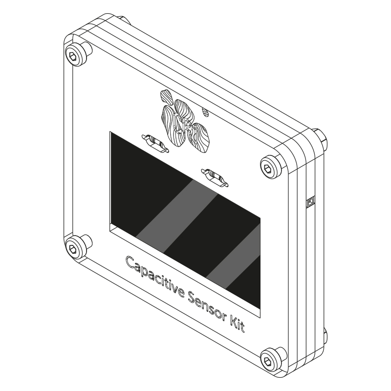
CAPACITIVE SENSOR
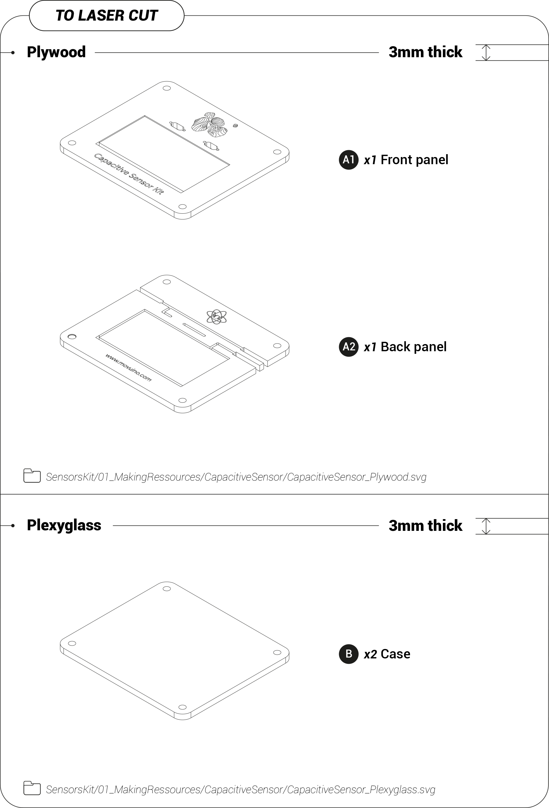
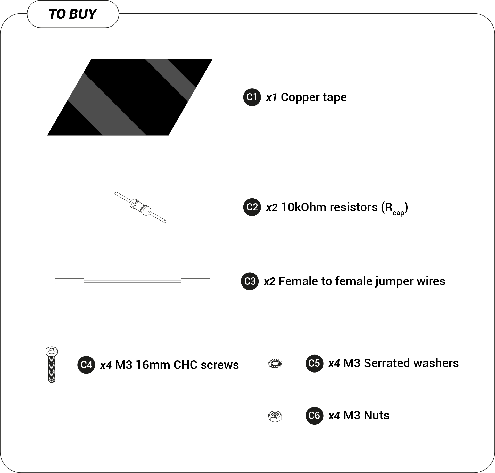
Furnitures
Get all the files you’ll need and start following the tutorial
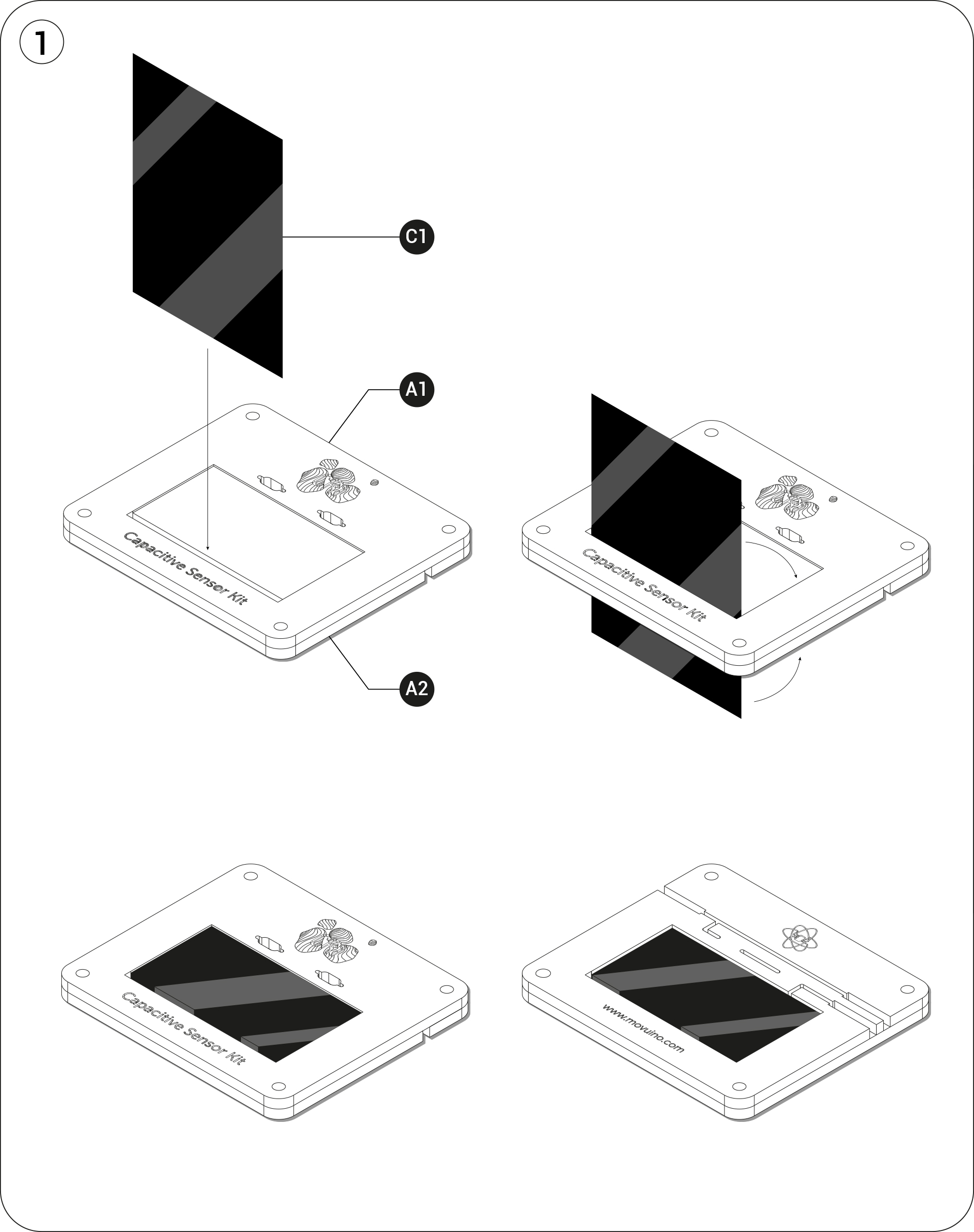
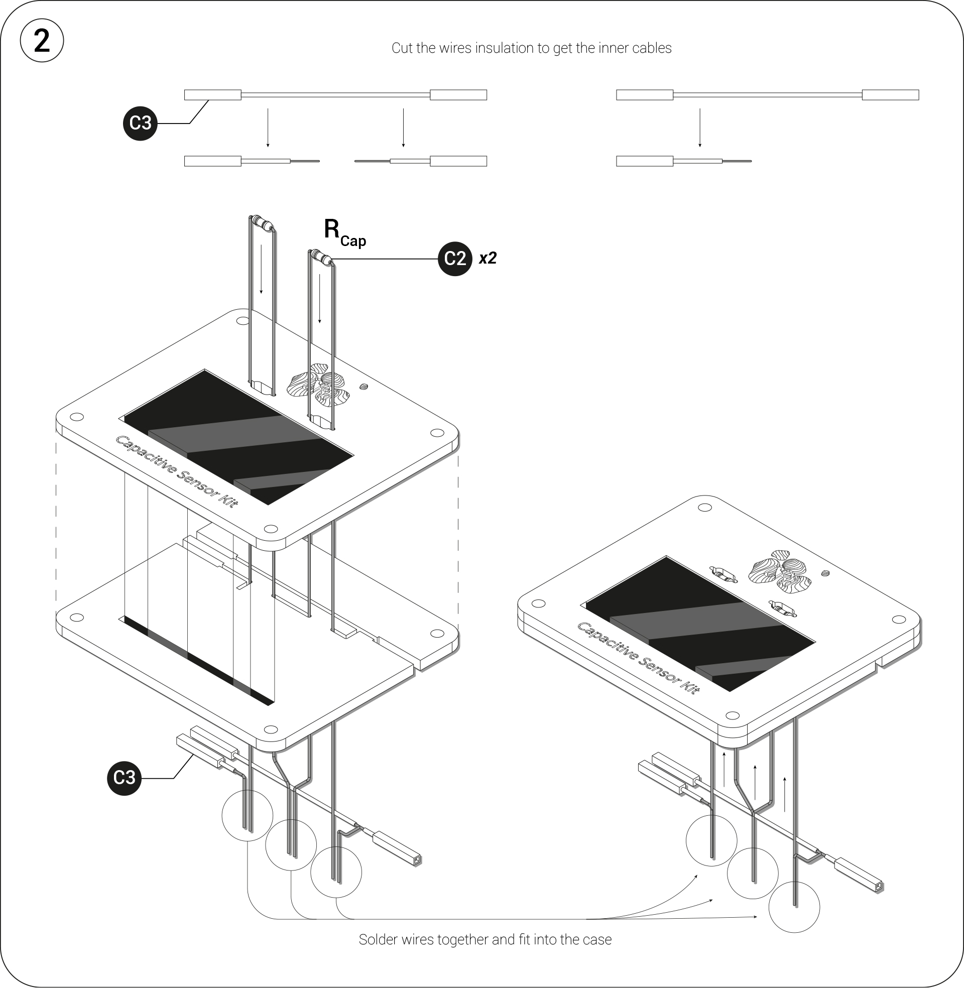
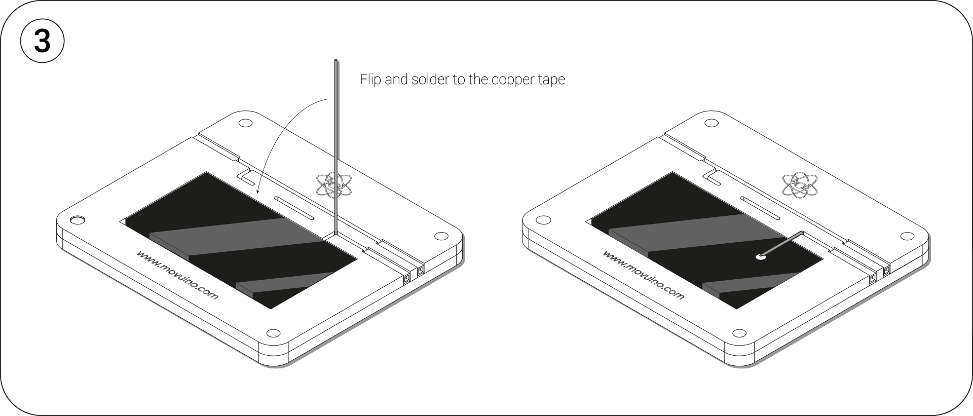
Assembly
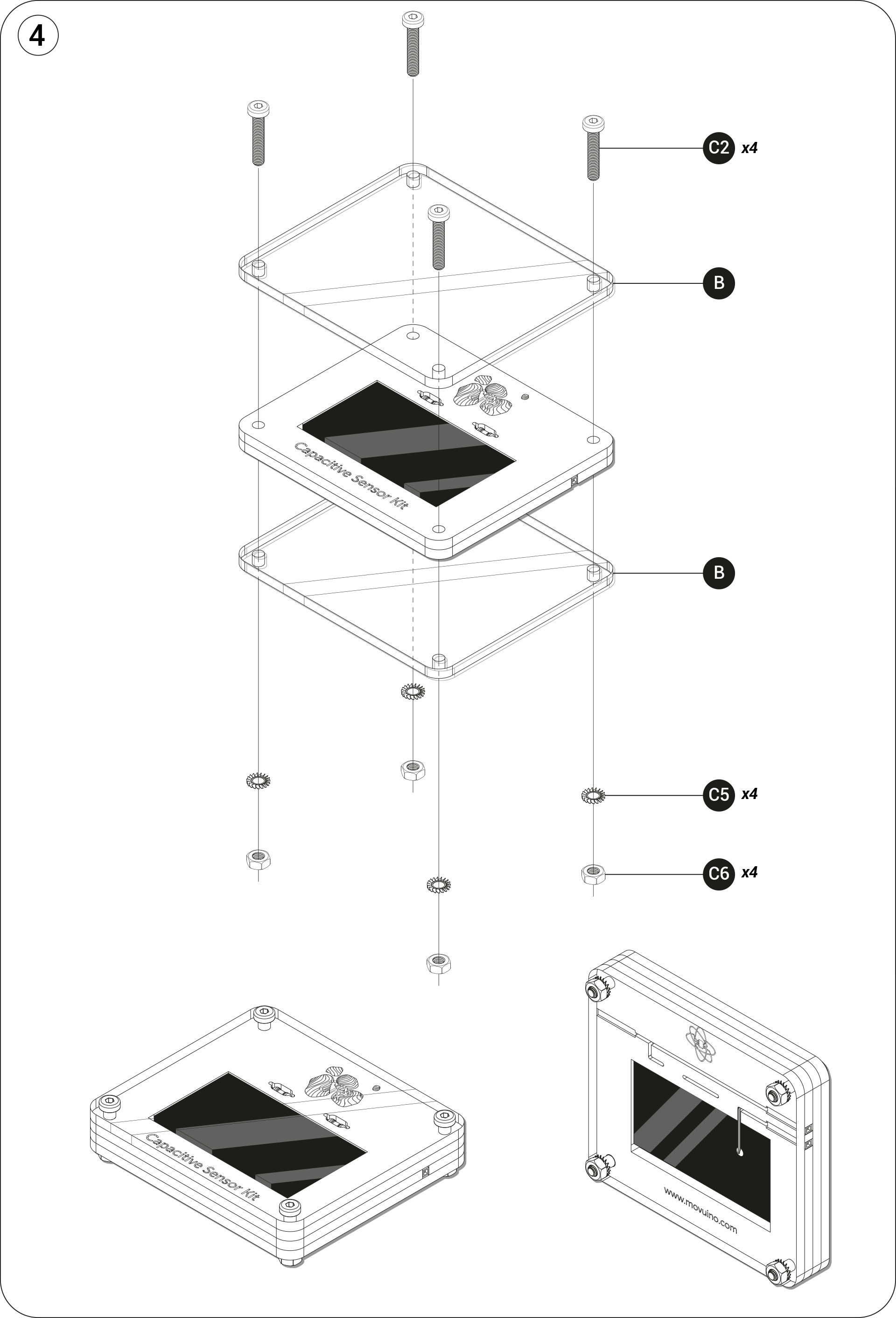
RESISTIVE SENSOR
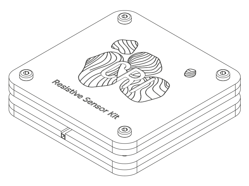
Furnitures
Get all the files you’ll need and start following the tutorial
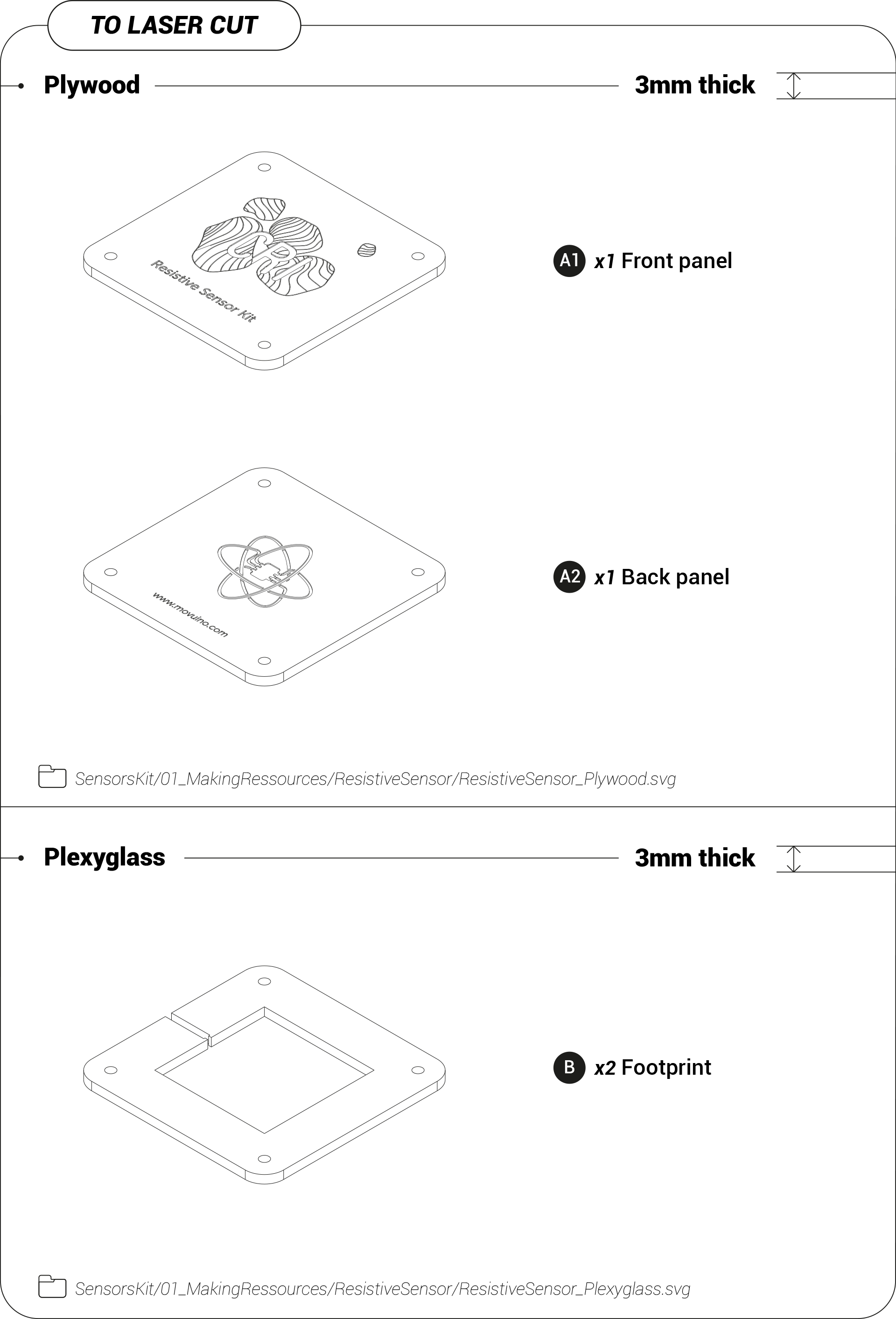
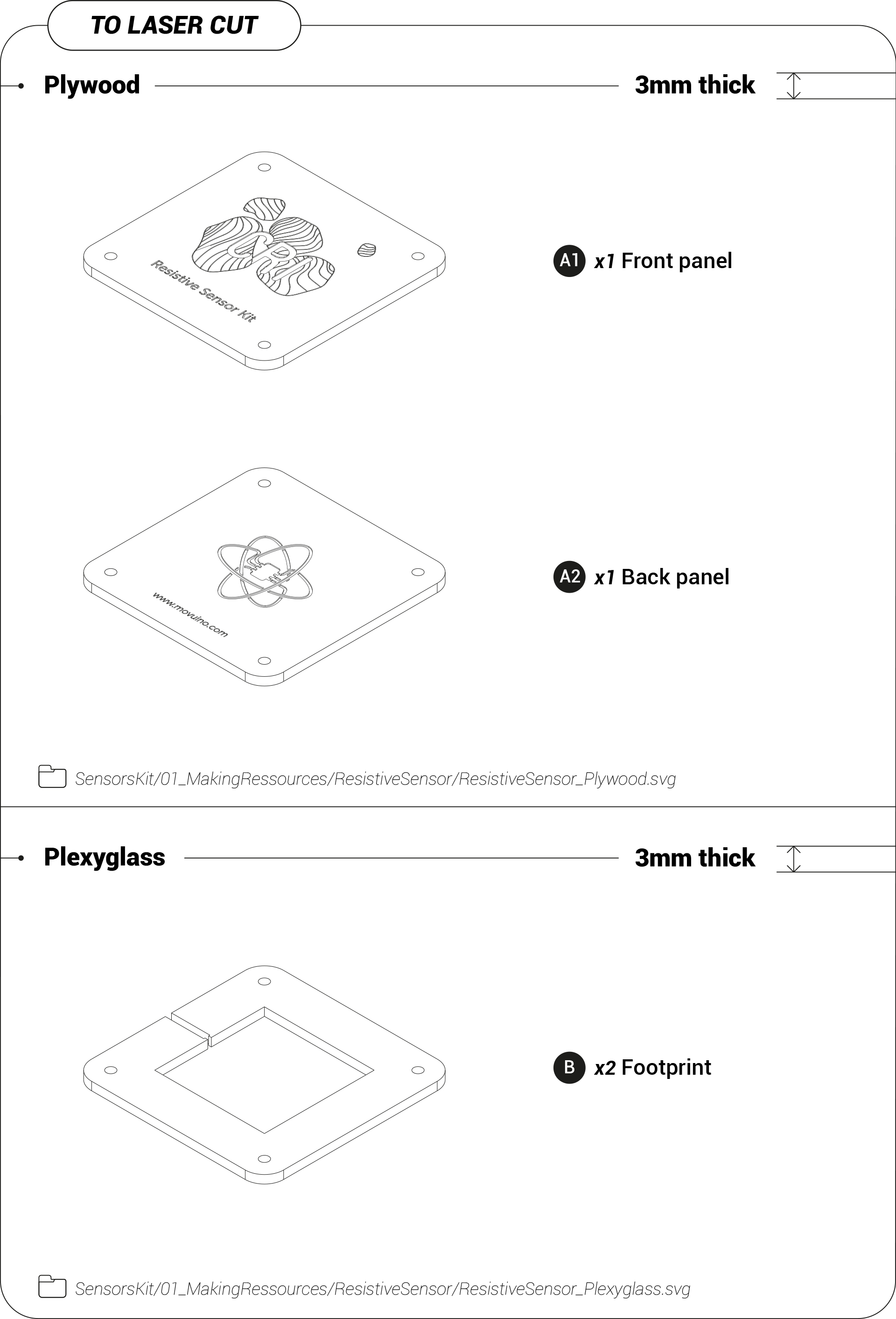
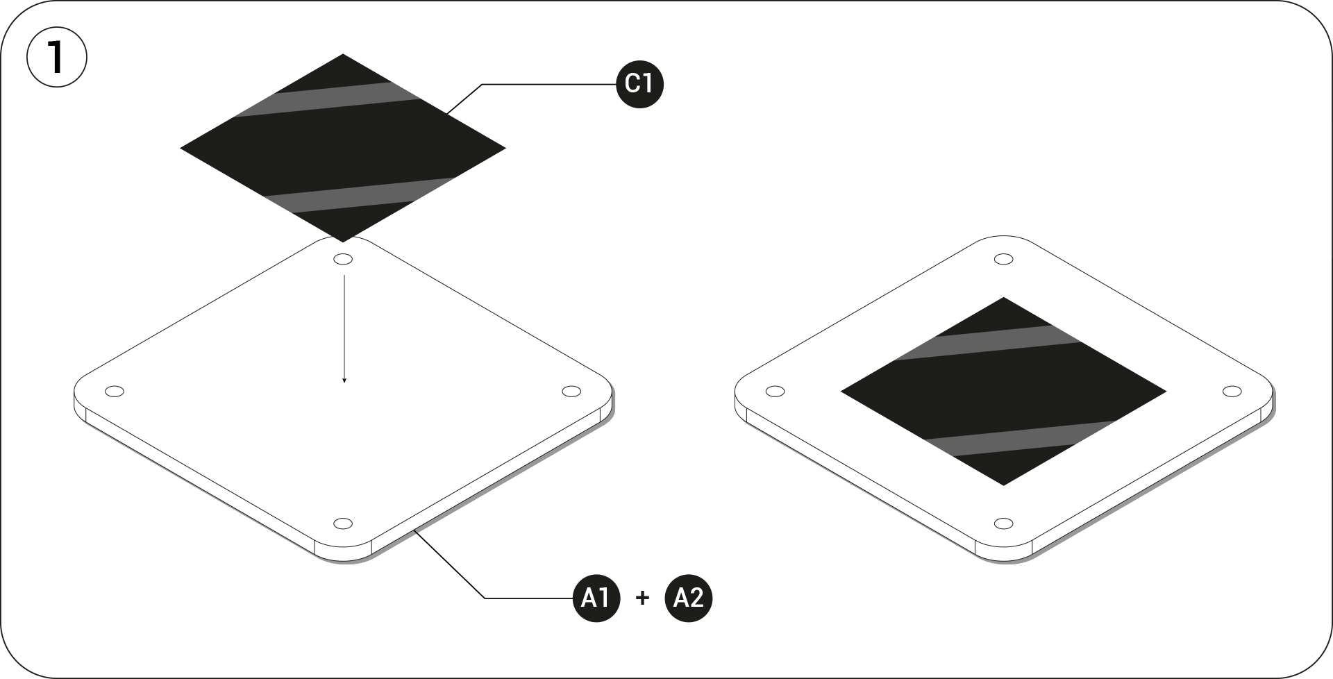
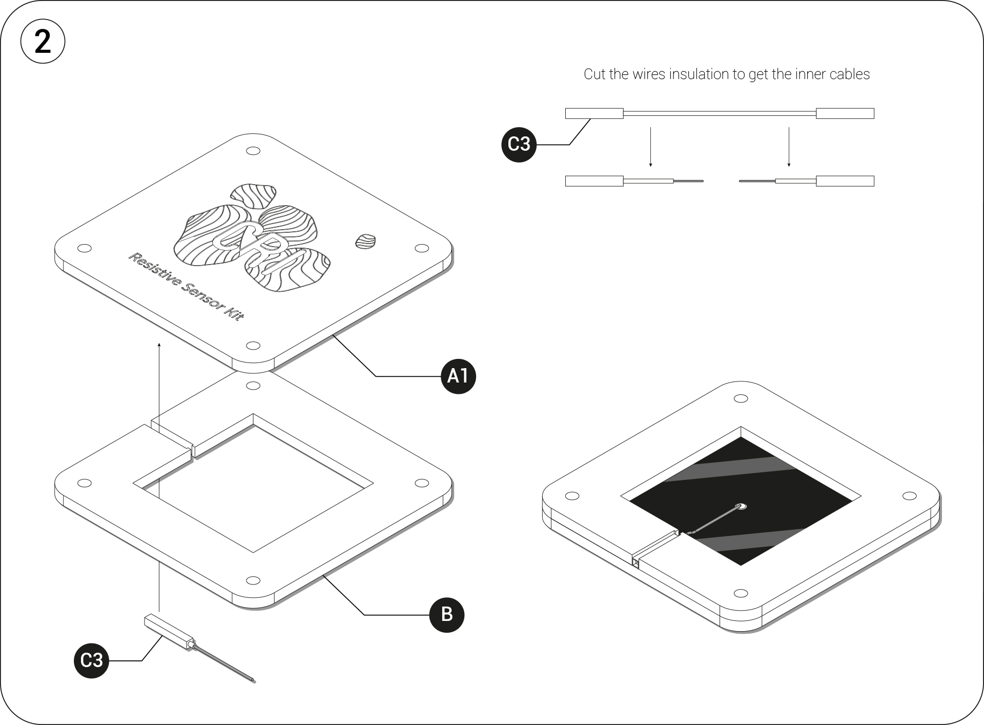
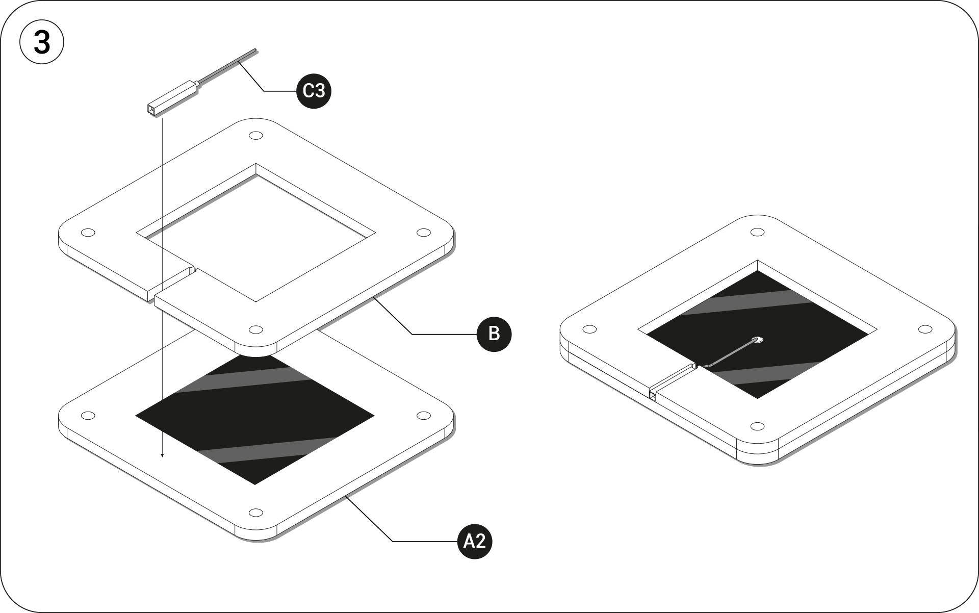
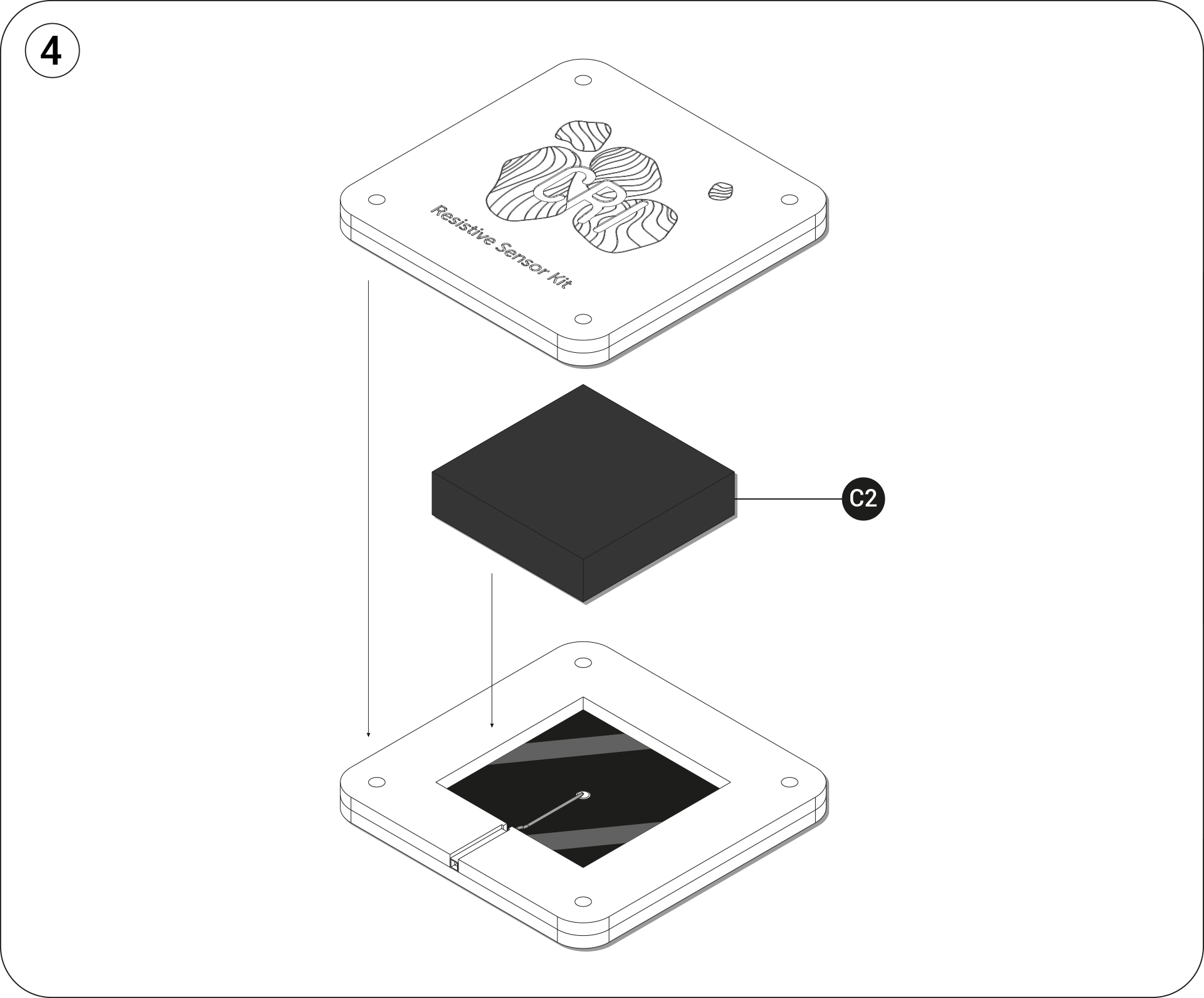
Assembly
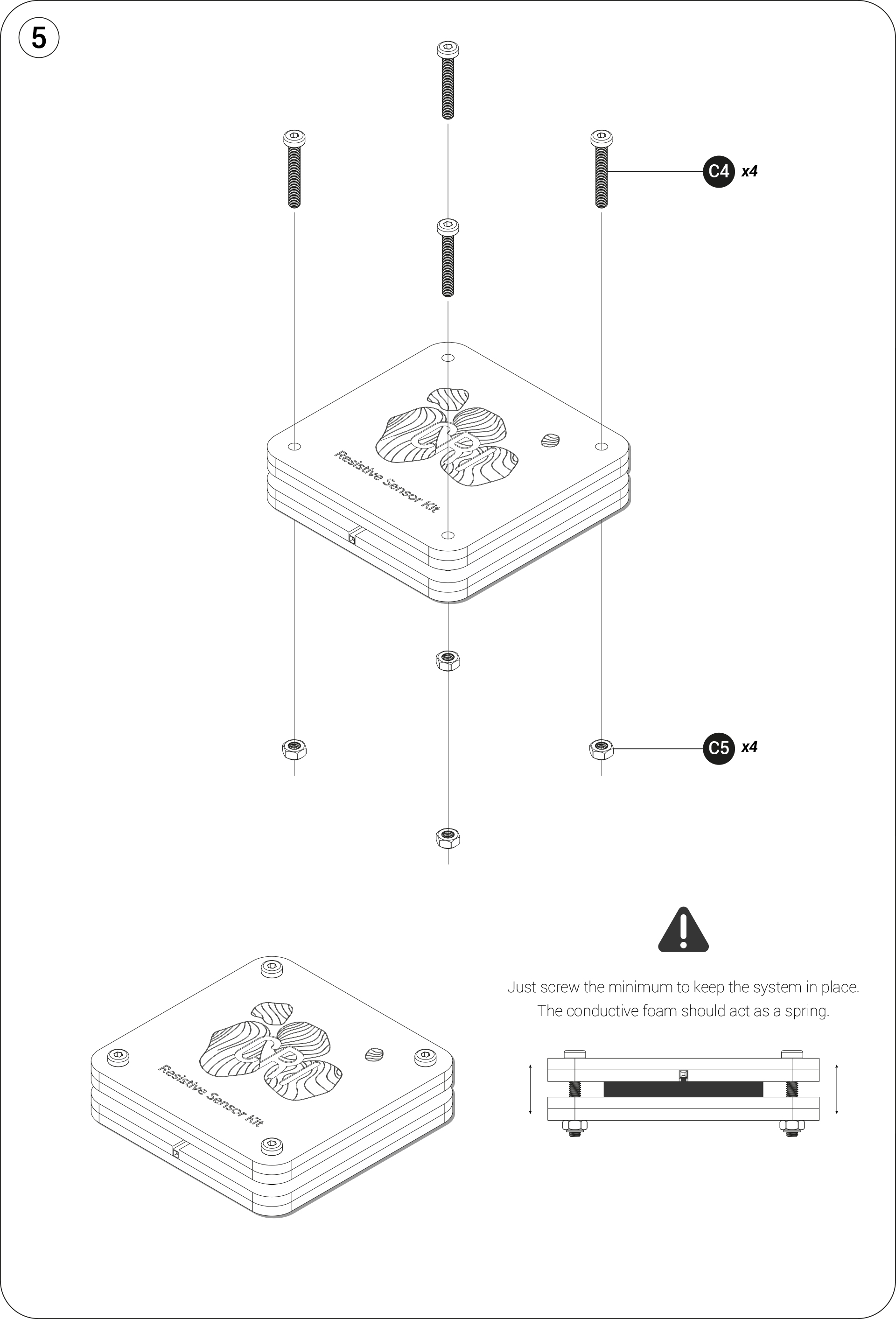
LED DISPLAY
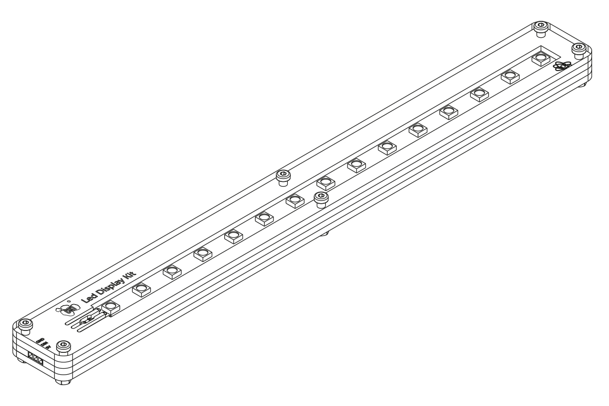
Furnitures
Get all the files you’ll need and start following the tutorial
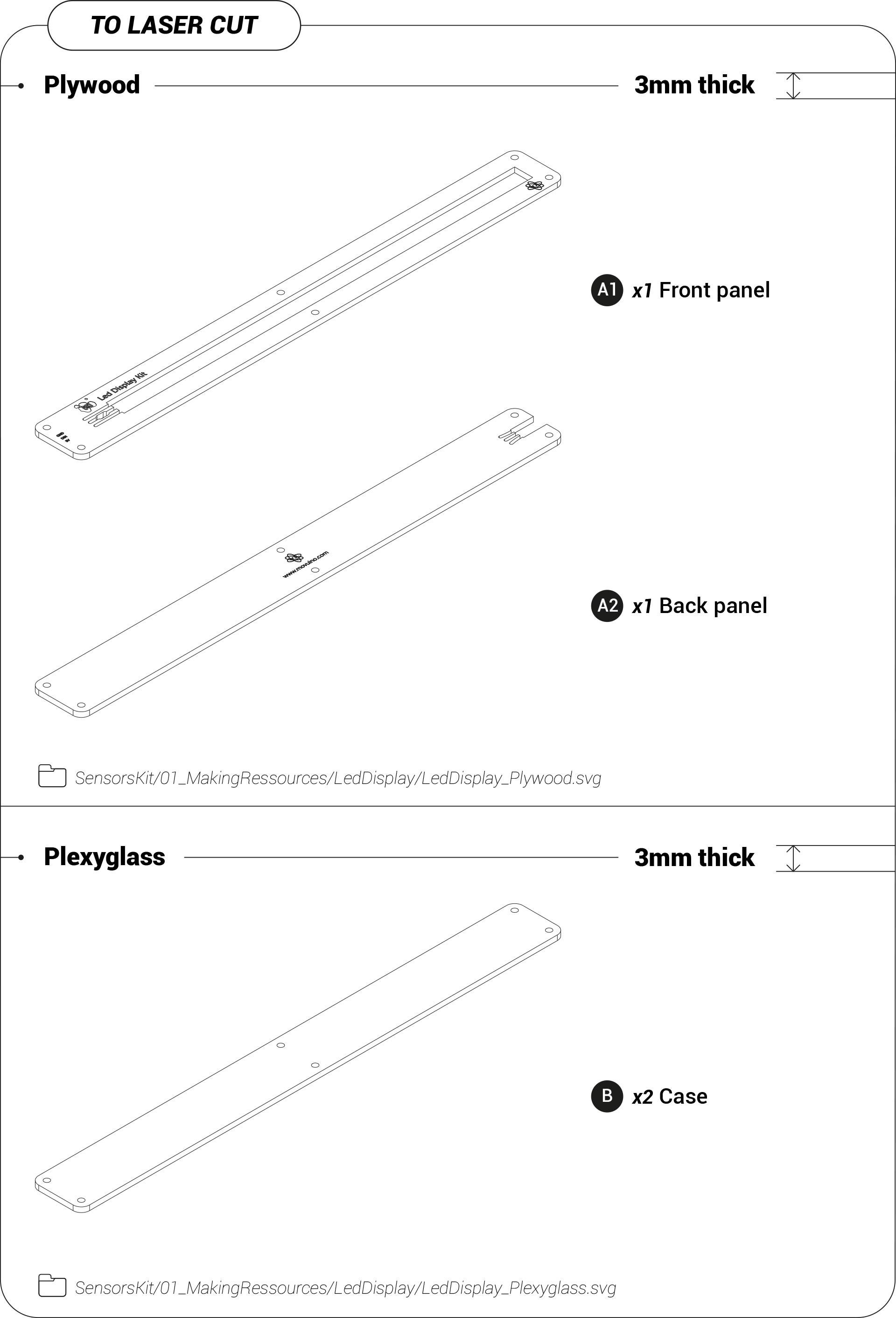
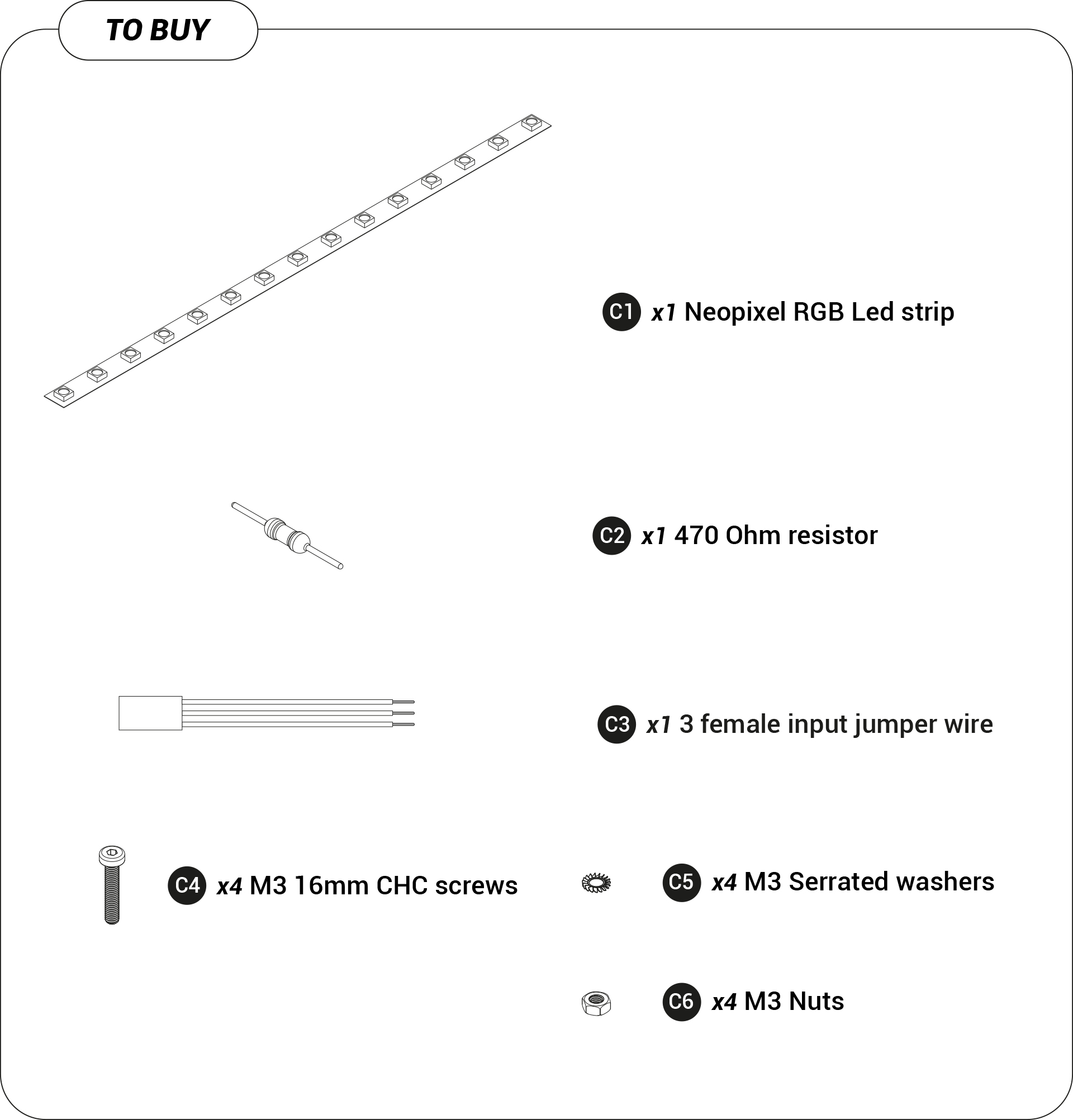
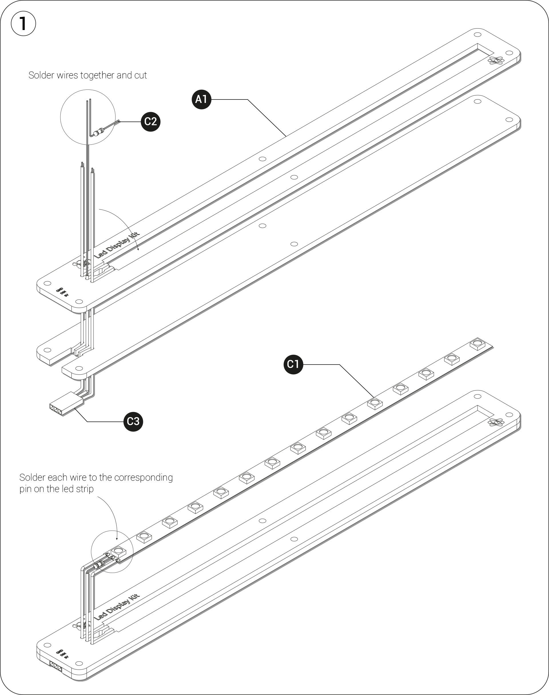
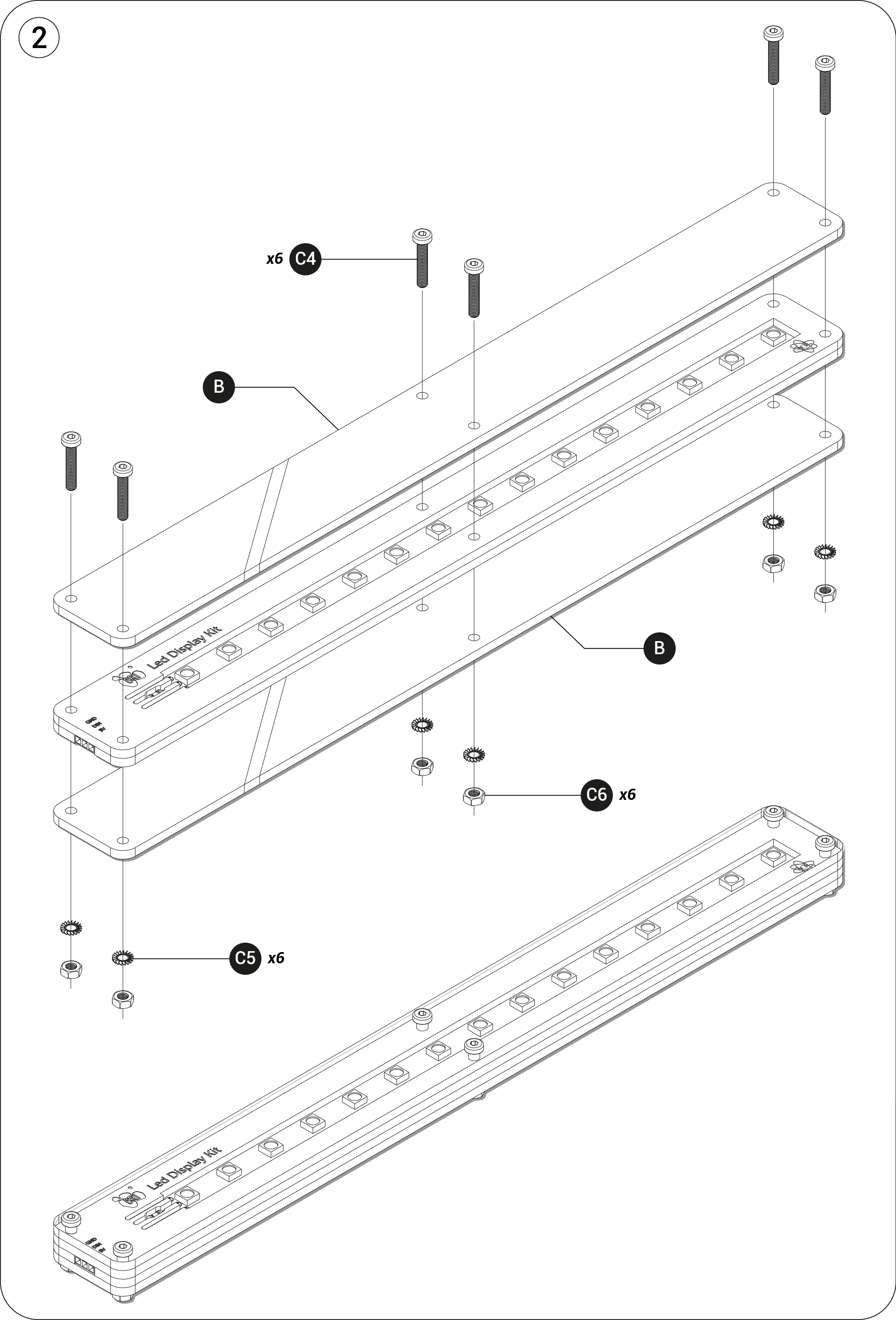
Assembly
VOLTAGE DIVIDER
Demo
This demo highlights voltage divider’s application.
By pressing the Resistive Sensor with your hand, you see the led strip reacting in function of the amount of pressure you apply.
The Resistive Sensor acts like a variable resistance, the more you press it, the more the current pass through the resistive foam and so the more its inner resistance descreases.
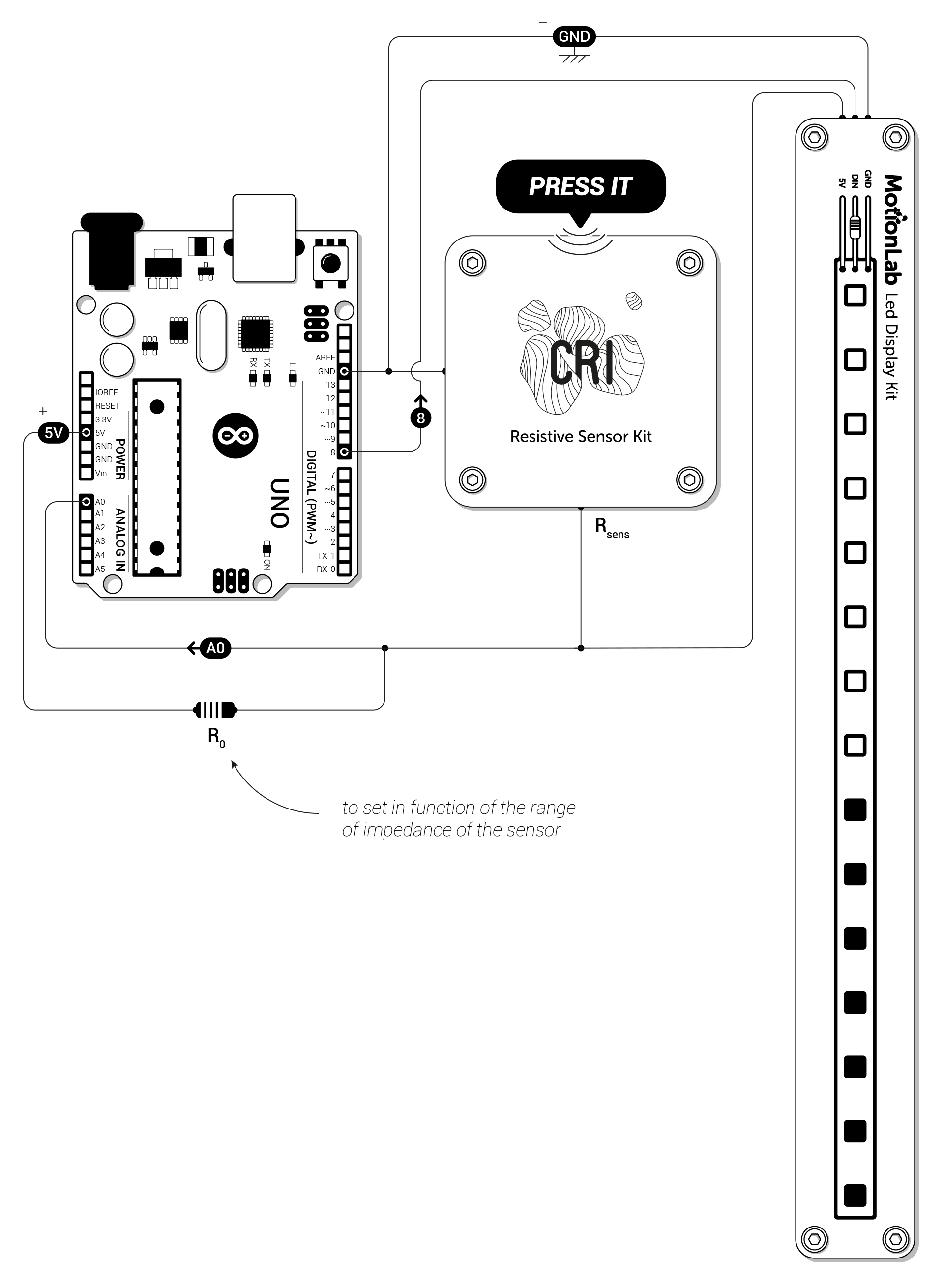

- Run the ResistiveDisplay.ino firmware with Arduino
-
You’ll need to install the Adafruit Neopixel library:
Sketch/Include a library/Manage libraries
- Search for «Adafruit Neopixel» in the search tab and the install latest version
- Upload the program on your Arduino board

Principle
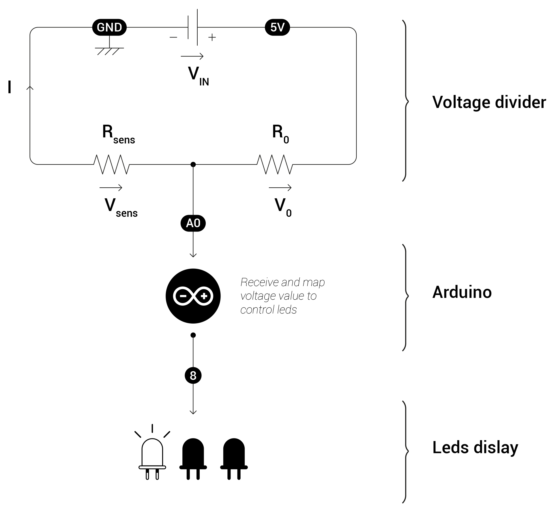
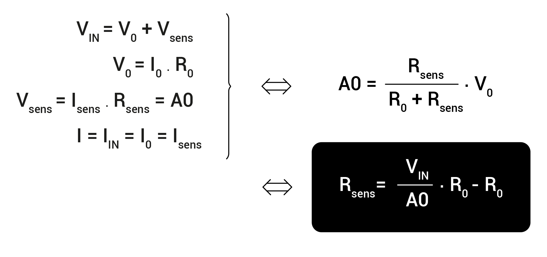
Formulas
Applying mesh analysis and Ohm’s law on the previous schematic highlights the direct link between the sensed tension (with A0 on the Arduino), the resistance variation of the sensor and thus the pressure applied on the sensor.
RC CIRCUIT
Demo
This program highlights RC circuit’s application.
By approaching the Capacitive Sensor with your hand, you see the led strip reacting in function of the distance to the sensor.
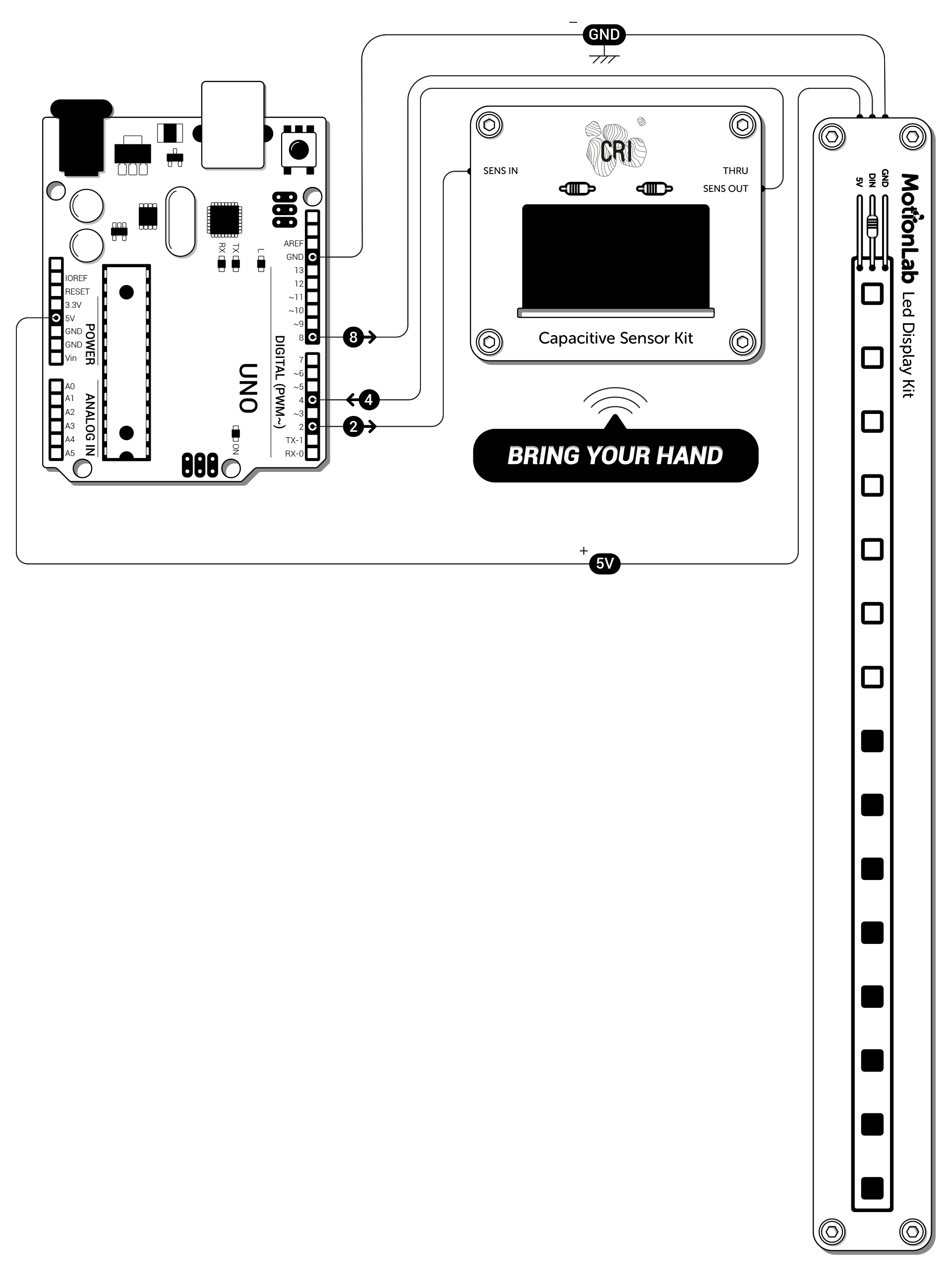

- Run the CapacitiveDisplay.ino firmware with Arduino
-
You’ll need to install the Adafruit Neopixel library:
Sketch/Include a library/Manage libraries
- Search for «Adafruit Neopixel» in the search tab and the install latest version
- Upload the program on your Arduino board

Experiences
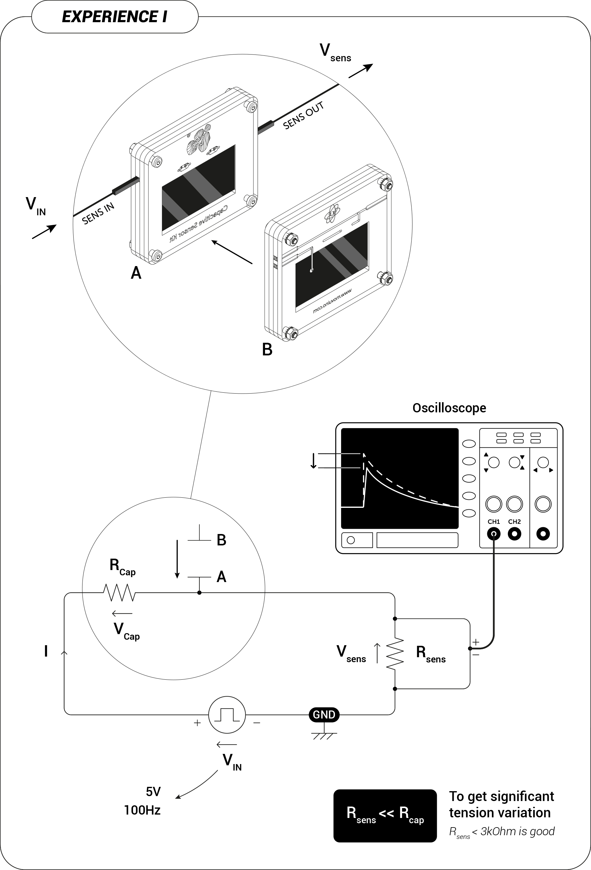
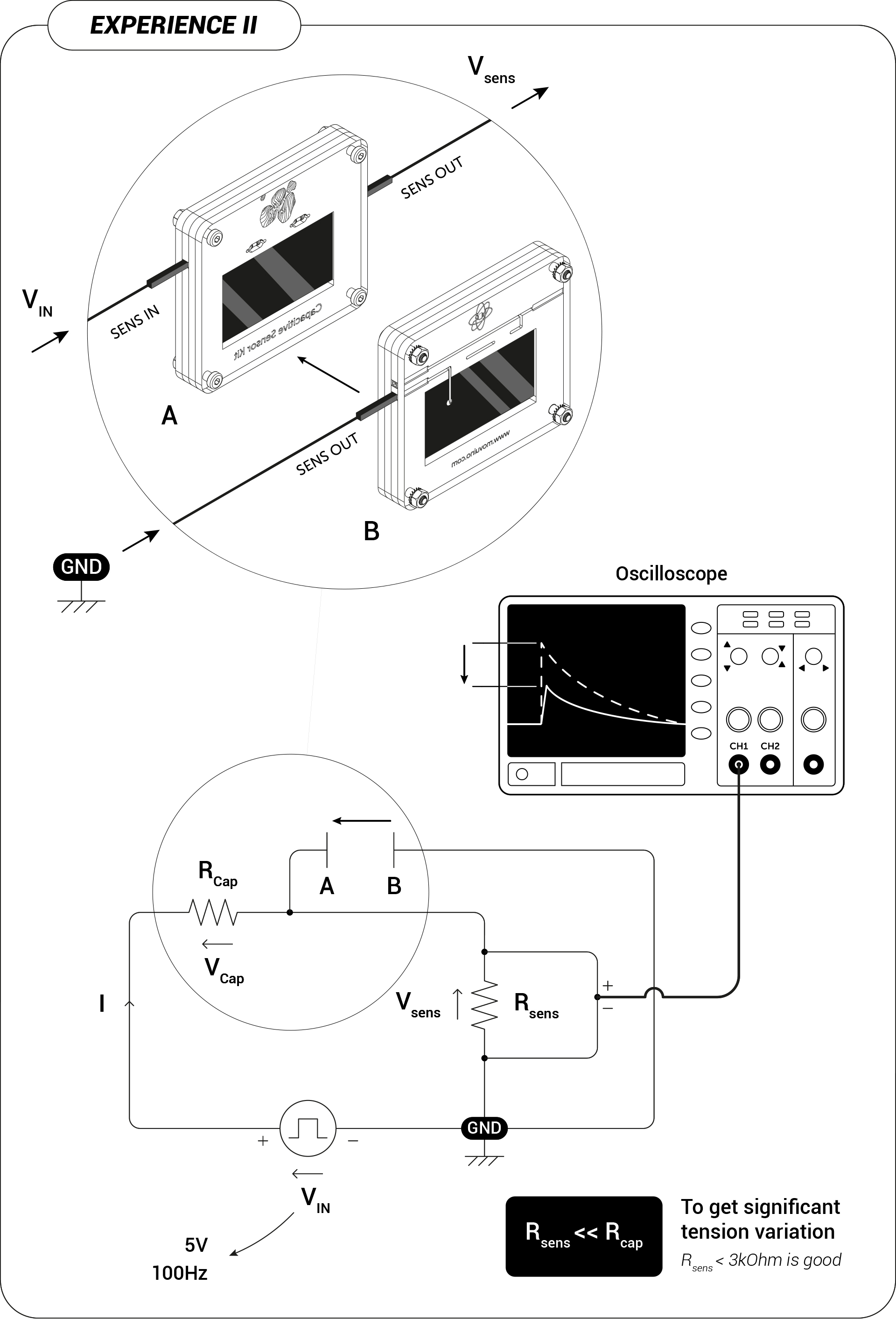
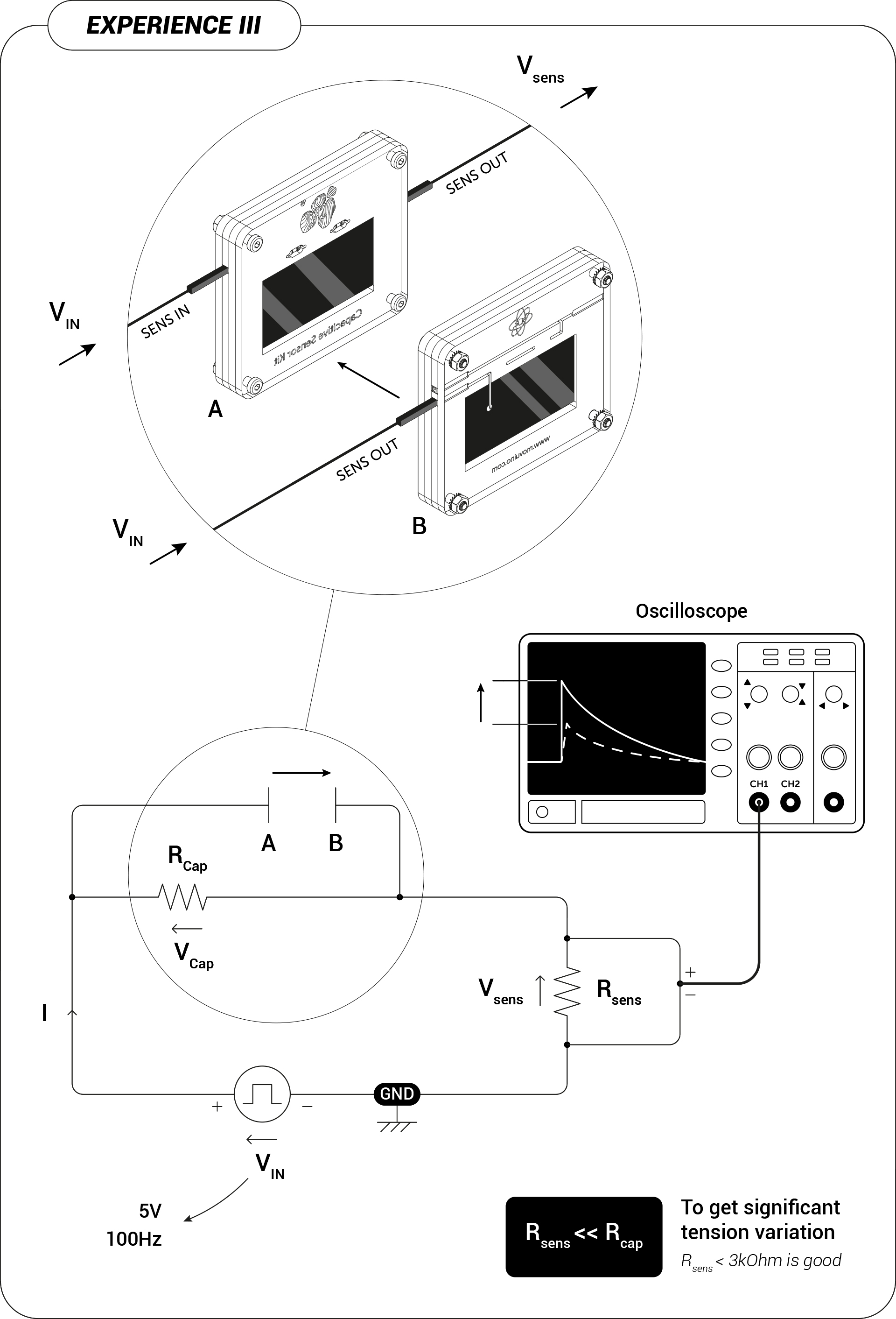
Principle
The principle behind those Demo/Experimences are based on the capacitor charging/discharging phenoma of an RC circuit.
In the Experiences part we illustrated the capacitor discharge, here are the classical schematic and the formulas related to this circuit.
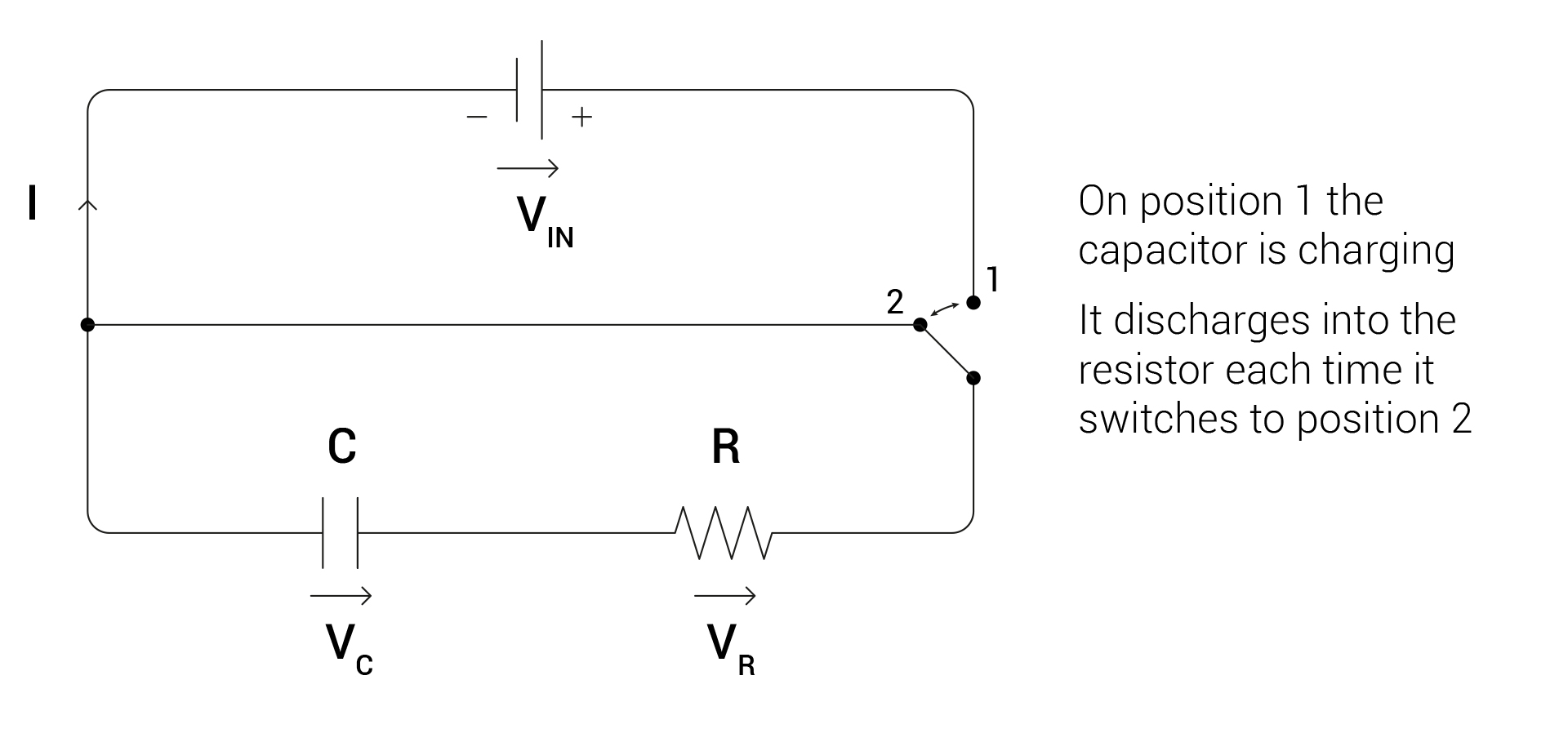
Following Vc over time reveals the characteristic equation of an RC circuit during the discharge
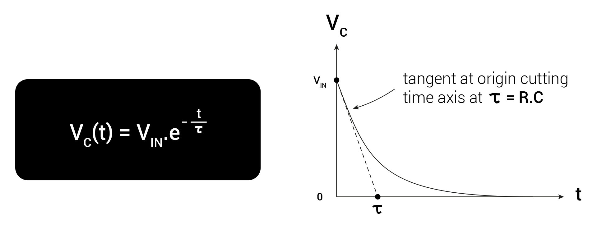
The time to load/unload the capacitor is directly related to the RC constant of the circuit.
By varying the distance between the 2 capacitive sensors, this modify the C constant which affects its load/unload time reaction.
In the Demo part, the interuptor is replaced by the pin 2 of the Arduino which simulate a square tension generator as you can use in the Experiences part.
Then the Arduino calculates the time to reach a significant tension value on its pin 4 and thus can give an estimation of C variations reflecting the distance variations between the 2 capacitive sensors.

